2020 官网升级中!现在您访问官网的浏览器设备分辨率宽度低于1280px请使用高分辨率宽度访问。
Product Introduction
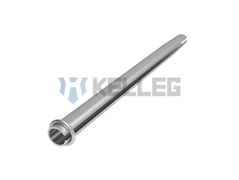
Split set is a new type anchor of full-length anchoring and active reinforcement of surrounding rock. It is composed of anchor rod and tray. The anchor rod is made of high-strength steel pipe and has longitudinal slits. When it is installed in a borehole slightly smaller than the pipe diameter, it can immediately apply radial pressure to the borehole through entire length and prevent the surrounding rock from sliding down. Coupled with the supporting force of tray, the surrounding rock is in a three-direction stress state to achieve rock stability.
Application Fields: It is mainly used in mine engineering, which can quickly provide supporting force to achieve better supporting effects.
Advantage
1. High-strength alloy strip steel is used as raw material. One end is forged with a tapered head for the anchor bar to insert the hole, and the other end is welded with an iron hoop to bear the weight of the plate.
2. Installation is simple and can be completed only by impact.
3. Anchorage agent is not required.
4. The friction between the anchor bar and the rock mass is high.
5. It has high shear and tensile strength.
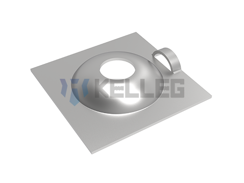
6. Equipped with a high-strength tray, the tray is evenly stressed.
7. The drilling depth is greater than the anchor bar depth.
8. It can provide timely support in radial and axial directions. It is unfit for permanent support in soft rock.
Product Parameters
Split set is mainly composed of anchor rod and tray.

Anchor Rod: The circular pipe formed by the thin plate is rolled into a tubular shape and has a full-length longitudinal seam, which is used as a bolt in the support field. There are two wall thicknesses, 2.5mm and 3.0mm.

Tray: The shape is square, with a bowl-shaped protrusion in the middle, which is a component that transmits the tensile force of the bolt to the surrounding rock.
Common specifications: φ30, φ35, φ39, φ43, φ46.
Product specifications
Anchor Rod
| Rod Dia. (mm) | Specification | Ultimate Tensile Load (KN) | Tensile Force of Ring (KN) | Cross Section Area (mm2) | Material | Recommended Drilling Hole Dia. (mm) |
|---|---|---|---|---|---|---|
| 33 | KFS33×2.5 | 100 | 75 | 214 | Q235 | 28~32 |
| KFS33×2.5 | 110 | 80 | 214 | Q355 |
| Rod Dia. (mm) | Specification | Ultimate Tensile Load (KN) | Tensile Force of Ring (KN) | Cross Section Area (mm2) | Material | Recommended Drilling Hole Dia. (mm) |
|---|---|---|---|---|---|---|
| 33 | KFS33×3.0 | 110 | 80 | 253 | Q235 | 28~32 |
| KFS33×3.0 | 120 | 80 | 253 | Q355 | ||
| 39 | KFS39×2.5 | 110 | 80 | 251 | Q235 | 35~38 |
| KFS39×2.5 | 120 | 95 | 251 | Q355 | ||
| KFS39×3.0 | 120 | 95 | 297 | Q235 | ||
| KFS39×3.0 | 140 | 105 | 297 | Q355 | ||
| 43 | KFS43×2.5 | 115 | 90 | 283 | Q235 | 39~42 |
| KFS43×2.5 | 130 | 105 | 283 | Q355 | ||
| KFS43×3.0 | 130 | 105 | 335 | Q235 | ||
| KFS43×3.0 | 140 | 110 | 335 | Q355 | ||
| 46 | KFS46×2.5 | 120 | 100 | 299 | Q235 | 42~45 |
| KFS46×2.5 | 140 | 110 | 299 | Q355 | ||
| KFS46×3.0 | 140 | 110 | 354 | Q235 | ||
| KFS46×3.0 | 165 | 120 | 354 | Q355 |
Tray
| Rod Dia. (mm) | Specification | Length (mm) | Thickness (mm) | Bearing Capacity | Material | Weight (kg) |
|---|---|---|---|---|---|---|
| 33 | KFS33-150×150×4 | 150 | 4 | 70 | Q235 | 0.63 |
| KFS33-150×150×4 | 150 | 4 | 80 | Q355 | 0.63 | |
| 39 | KFS39-150×150×4 | 150 | 4 | 70 | Q235 | 0.62 |
| KFS39-150×150×4 | 150 | 4 | 80 | Q355 | 0.62 | |
| 43 | KFS43-150×150×6 | 150 | 6 | 80 | Q235 | 0.94 |
| KFS43-150×150×6 | 150 | 6 | 90 | Q355 | 0.94 | |
| 46 | KFS46-150×150×6 | 150 | 6 | 80 | Q235 | 0.94 |
| KFS46-150×150×6 | 150 | 6 | 90 | Q355 | 0.94 |
For more product specifications, Please email us at info.k@kellegco.com or leave us a message, Kelleg will provide you with professional and prompt reply.
Installation precautions
1. Determine the drill hole position according to design requirements, and then make the hole with a drill.
2. Use compressed air to blow away the rock dust in the hole.
3. Fit the anchor rod with plate, and drive the rod into the hole with percussion drill.